
In this chapter
Before the first power up
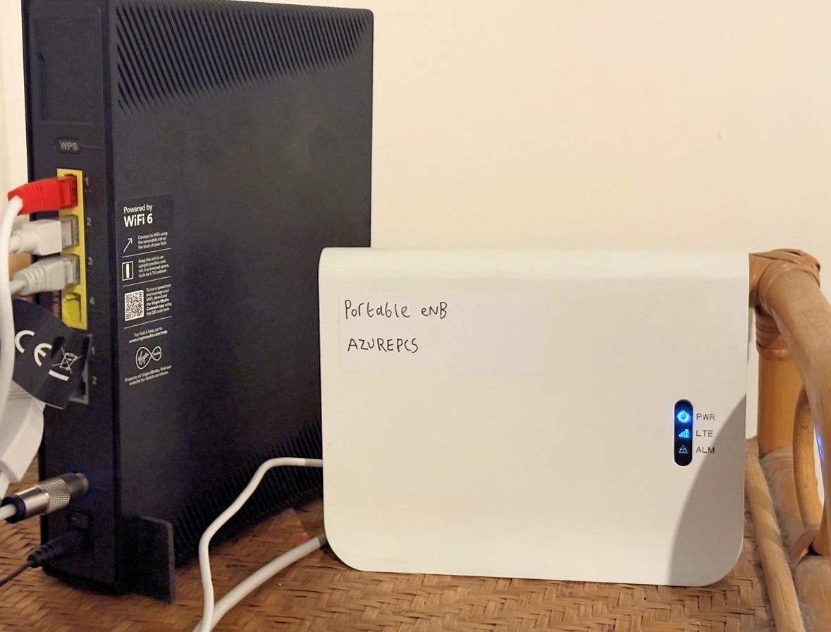
Check the label, model suffix, band, power supply and PoE standard. A device that looks identical can contain a different radio board. Some Baicells firmware enables RF by default. Arrange a licensed and compliant setup or an appropriate screened test arrangement before powering equipment that may transmit. Never assume that leaving it unconfigured makes it silent.
Follow the manufacturer's antenna instructions. Do not remove an antenna or operate an external-antenna transmitter into an open connector as a way to silence it. Use correctly rated equipment and qualified help for screened or conducted testing.
- Put the radio in the indoor licensed location with suitable ventilation and safe power.
- Connect its data port through the correct PoE injector or switch to the isolated radio network.
- Identify its factory management address from the exact manual or the supplier's setup sheet. Do not guess a default password from an unrelated model.
- Give a directly connected maintenance computer a temporary compatible address if the manual requires it. Do not create a bridge to the Internet.
- Log in, disable RF in the supported menu, change the administrator password and save a backup of the original configuration privately.
Update safely and choose an external EPC
Obtain firmware from the manufacturer or the authorised supplier for that exact hardware. Record the current version and the recovery procedure before updating. A wrong image can make the radio unusable. Do the upgrade while service is stopped, then verify that RF remains disabled afterwards.
In firmware that offers a CloudEPC or EPC mode option, select the supported external or local EPC mode. The public Nova227 product information and its linked configuration manuals explain the product family, but menu names vary. Some shared manuals describe other models. Use the interface fields below as a translation worksheet, not a claim that every Baicells screen is identical.
Enter the wired network settings
These are the single-PC Open5GS addresses. For the VectorCore branch, use its separate address plan: radio 10.77.0.40, MME 10.77.0.10 and serving gateway 10.77.0.20. Do not mix the two example plans.
| Field or concept | Worked LAN setting | Reason |
|---|---|---|
| WAN or S1 address | 192.168.200.10/24, static | A stable address on the dedicated radio Ethernet. |
| Gateway | 192.168.200.1 | The Ubuntu PC on that Ethernet. No general forwarding is granted by default. |
| MME address | 192.168.200.1 | The address where Open5GS MME listens. |
| S1 signalling | SCTP 36412 | Not TCP 36412. A router/firewall must understand SCTP if present. |
| User data | UDP 2152 to the core’s advertised SGW-U address | A working MME link alone does not prove the data path. |
| IPsec | Disabled for this directly connected, trusted LAN build | No tunnel is needed just to cross a private Ethernet cable. |
| VLAN | None unless deliberately planned | Both ends must use the same tagging plan. |
| Management services | Local only, unique administrator password | No public forwarding or default credentials. |
After saving a new management address, reconnect your maintenance computer to the planned subnet and log in at the new address. A browser losing contact during an address change is expected. Write the new address down before saving it.
The baseline firewall blocks general radio Internet access. If this model needs a network time server, cloud licence check or vendor service, identify the exact requirement before adding a narrow rule. GPS or supported PTP timing may satisfy the radio timing requirement without general Internet forwarding. NTP is a separate wall-clock service.
Enter the mobile identity
| Field | Example | Check |
|---|---|---|
| MCC | 999 | Private network example only. |
| MNC | 99 | Two digits, consistent with IMSI and MME. |
| TAC | 1 decimal | If the screen expects hexadecimal, confirm the equivalent value. |
| eNodeB ID | A unique lab identifier such as 1 | Coordinate identifiers before adding another cell. |
| Cell ID | A unique local cell identifier | Follow the model’s allowed range. |
| Network selection | Your planned private PLMN | Do not broadcast Lodestar’s or another operator’s identity. |
The phone's displayed network name is not an authentication test. A device can show an old SIM service-provider name even when the PLMN is correct. Judge the connection by the actual selected PLMN, attachment result and data session.
Enter only the licensed radio settings
Copy the assigned frequency, bandwidth, indoor restrictions and power conditions from the issued licence into your settings sheet. For illustration only, a licence for a 10 MHz carrier covering 2390 to 2400 MHz corresponds to a centre of 2395 MHz and Band 40 EARFCN 39600. That example is not permission to transmit. Do not choose 20 MHz for a 10 MHz grant.
Set the permitted output using the manufacturer's interpretation of per-chain power, antenna gain and total EIRP. The spectrum chapter includes the worksheet. A radio that supports a high output does not have permission to use it.
Select the TDD uplink/downlink pattern and special subframe pattern required by the licence, coordination and equipment support. Do not select a guessed pattern from a distant operator's tutorial. Nearby TDD networks can interfere when their timing and direction disagree. Confirm GNSS/PTP lock, alarm state and the intended timing source before enabling RF.
Bring up the wired S1 connection first
Where the firmware allows it with RF disabled, check that the core connection becomes established. The MME log should show an eNodeB S1 setup, not a handset attachment yet. On the Ubuntu PC, useful checks are:
ping -c 3 192.168.200.10
sudo ss -lnp -A sctp
sudo journalctl -u open5gs-mmed -n 60 --no-pager
sudo tcpdump -ni enp2s0 'host 192.168.200.10 and sctp port 36412'
Ping only proves IP reachability. SCTP and an accepted S1 setup prove more. Press Ctrl+C to stop a capture. Signalling captures can contain subscriber identities once phones join, so keep them private. Some firmware does not establish S1 until the radio is enabled; in that case complete the settings, licence and timing checks first, then use the controlled activation in the next chapter.
Checkpoint
Save a configuration backup with its firmware version, model and date. Confirm the radio has the intended private address, external EPC settings, PLMN and TAC. Record the actual licensed RF settings separately from the example. Keep RF disabled until every item in the next chapter's activation check passes.